| This section describes how blue color measurements can be done with CooRecorder. The mechanisms for these measurements can also be used to estimate density from gray scale images created from X-ray scans, which is further described in another section. |
|
Blue color intensity measurements on latewood may be an inexpensive way to rapidly access paleoclimatic information, i.e. temperature in earlier years. Density data is known to be related to temperature, though density is difficult and expensive to measure. Recent studies indicate that blue color intensity measurements could be used as kind of a poor mans substitute for density measurements. By measuring the difference between the color intensity from earlywood and from latewood we can demonstrate a positive correlation to the width of tree rings. This sounds great, though useful blue channel measurements require chemical treatment of the wood samples to first remove resin, i.e. "cooking the wood in alcohol" (Soxhlet extraction). This process requires a laboratory with suitable equipment and precautionary measures to avoid severe hazards! Recent work behind these studies are reported in:
Mauri Timonen at METLA has edited a list at [view PDF] with also these items: |
|
My own measurements on blue color have been done on Scots pine (PISY) and on Norway Spruce (PCAB).
I have found that data series created from the difference between blue color intensity from earlywood and from latewood ("delta-blue") often has a high positive correlation
to the corresponding ring width series. (The minimum blue color from only the latewood has a negative correlation towards the ring width series.)
As an example in this section, I have used series of ring width and of delta-blue values from a trunk of Scots pine from the island of Nämdö and compared that to a tree ring reference curve from that same island. This example shows a clear correlation (0.65) between the delta-blue values of the youngest 50 years of the sample while the oldest 34 years give a much lower correlation (0.42). I assume that this is because of a higher content of resin within the inner part of the trunk than within the outer part. We should then consider that the depositing of resin in the inner part of a Scots pine does (usually) not occur until the tree has become old. So the resin appears within the inner tree rings many years after those rings where formed by tree growth. The result of this late resin deposition might be seen as noise from late time, added to data from older times. The samples I have analyzed were not chemically treated at all. In spite of the high correlations described here, the case may anyhow be that useful blue color data from Scots pine to be used for climate analysis can only be retrieved after a Soxhlet extraction process has been done on the wood! |
How to measure blue channel data with CooRecorder

|
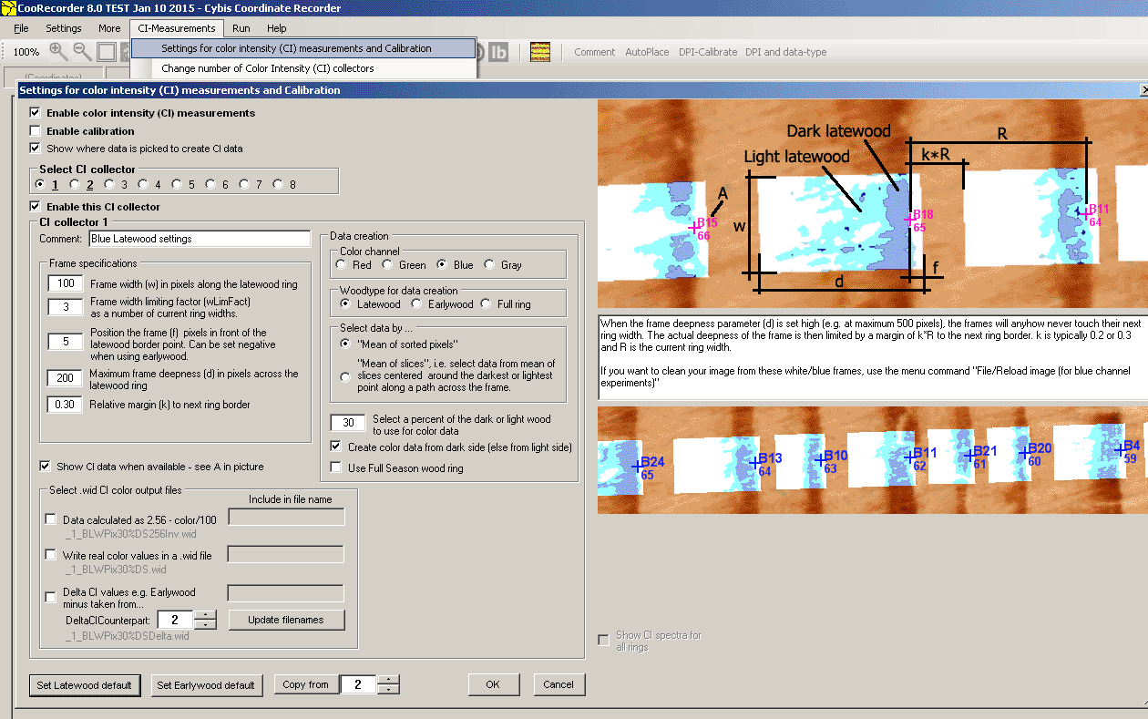
When doing blue channel measurements with CooRecorder we have to define where the measurements should be done.
The measurment rectangels (or frames) can be layed out in various ways across the latewood rings.
A number of parameters control how the frames are layed out.
We also have to define what data should be extracted and how it should be processed. E.g. should we collect latewood color and if so, how much of it? Should we look at individual pixels or should we always look at an aggregate of pixels? With different settings for collecting and processing data we will get different results. CooRecorder gives you tools to experiment with different settings. |
|
When you first open the CI-measurements/Settings for color intensity (CI) measurements and calibration,
see that the Enable color intensity (CI) measurements checkbox is checked!
If this box is not checked all other blue (or other color) channel settings are ignored! Checking this box also makes the lb-icon To also see the blue channel data (as e.g. "B87") while measuring, you have to set the checkbox "Show CI data when available - see A in picture". |
|
Frame size:
Note: CooRecorder will automatically identify light and dark areas within your frames. If you place the frames so there is normally no earlywood inside the frames, then CooRecorder will anyhow divide the frames into light and dark areas and then calculate the minimum blue channel values from the dark areas. Though the extent of the dark areas may then be a matter of chance. Frame settings are best when there is both earlywood and latewood inside the frames! |
|
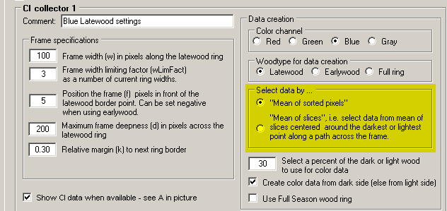
Select by "mean of sorted pixels" or by "mean of slices"A pixel has three colors, red, green, blue (RGB). Each color is represented as an integer in the range 0 to 255. Before we can calculate the mean value for latewood or earlywood pixels within a frame, we have to decide what is earlywood and what is latewood within that frame. Only then, we can calculate a mean value for the latewood and earlywood colors. We should even be able to calculate that value out of e.g. the darkest 30% of the data points. With CooRecorder 8.0 there are now two quite different methods for calculating the minimum latewood or maximum earlywood values. These methods differ when it comes to the "priority" of the individual pixel. Should the pixels' "voting" for a color shade be based on the "votes" from individual pixels or from small groups of individual pixels? In the first case we can count also the numbers of very extreme values and later allow for a selection of such values by using a low percentage value and start collecting data from the dark side of the pixel collection. In the second case each small group of pixels will deliver a mean value for the group. Normally this will never become very extreme. 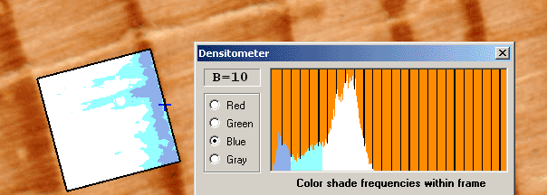
Mean of sorted pixels. 40% of the latewood selected from dark side. Mean of sorted pixels. With this method all pixels within a frame are sorted into 256 different boxes, one for each shade of blue (or what color you chose). After this sort we know how many pixels there are for each shade. Depending on the distribution of these values we can find a suitable value that divides the pixels into a light group and a dark group and we can find out how many pixels we have in each group. If we now want to know the mean value shade for 10% of the darkest or lightest pixels within one group this can easily be calculated. The consequence of this method is that extremely dark pixels scattered around the image can when sorted together produce a very dark mean value shade. Question is if this really mirrors an interesting property of the wood. Another phenomenon is that encapsulated light areas within the latewood will be considered as not being latewood and thus excluded from the latewood mean value shade. If this is good or not might be questioned. 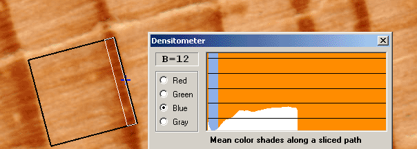
Mean of slices. 40% of the latewood selected from around the darkest slice. Mean of slices. With this method we first define a path across the frame. This path corresponds to the path used to set out the ring border points. We then slice the frame across the path and calculate a mean value shade for each slice. Like above we can divide these slices into light and dark ones. In this case we know in which order these "slice-shade" values lay along the path. We can therefore select the very darkest slice and calculate a latewood mean value shade from only nearby slices. This makes it possible to exclude any dark area that is not positioned within the actual latewood area of the ring. |
|

50% of the earlywood selected from light side ("Create color data from dark side (else from light side)" was UNchecked.) 
50% of the earlywood selected from around the lightest slice. Earlywood and a negative f-value. A negative f value is usually used when you want to extract earlywood data. A negative f will then prevent selection of earlywood belonging to the previous tree ring area. Medium blue, light cyan and white colors. When using the "Mean of sorted pixels" method, medium blue is used to mark those areas selected for your mean value color.
I.e. if you are colleting latewood, then medium blue marks e.g. the selected 30% of the latewood pixels, while light cyan (light blue-green) marks those 70% of the latewood pixels not selected.
White then marks those pixels considered as earlywood.
|
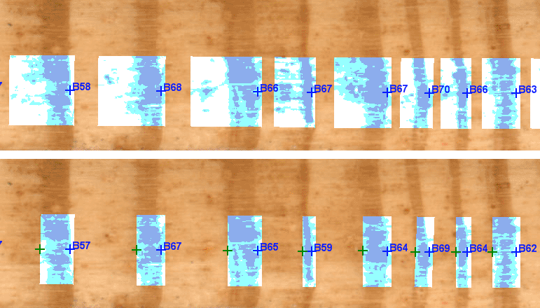
Measuring latewood with only ring border points (upper) or also with seasonwood points (lower). White areas are considered as earlywood. (NM115A) The actual frame deepness for "a latewood frame" will depend also on the existence of a seasonwood point, i.e. the frame will never extend beyond the seasonwood point and thus overlap only a minimum of the earlywood area. |
How to show the white/blue frames:
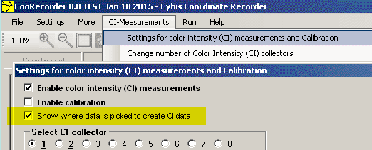
The white/blue frames shown are made visible by checking the checkbox "Show where data is picked to create CI data".
CI Collectors
As described above you can define a number of parameters for how color intensity (CI) data should be collected. There are even three checkboxes for you
to specify how your data should be saved. But all this is "for one setup". And this is how it worked with CooRecorder version 7.8
With CooRecorder 8.0 you can define up to 8 different "Color Intensity Collectors" (CI collectors) where each collector has its own settings like those described above.
This means that you can have one collector for collecting data from the full ring while you also have a collector for just the Latewood section and another collector
for the Earlywood section. You can even request data to be calculated as "light blue earlywood minus dark blue latewood", i.e. a "delta-Blue" calculation.
 To select a Color Intensity (CI) collector, look for the "radiobuttons array" shown above and click the appropriate button. There is also a checkbox to "enable" the selected CI collector.
Please note that when a collector is "enabled", its number will be written bolded together with an underline character, so that you can easily see which collectors will take
part in your operations.
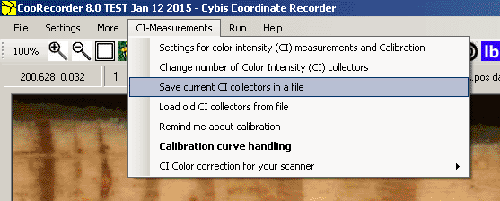 Note: If you want to save very different CI collector setups, e.g. if you are doing both Blue channel measurements and Density measurements, then you can save all your current CI collector setup with the command "CI-measurements/Save current CI collectors in a file" and later load them using the command "CI-measurements/Load old CI collectors from file". These files can also be used to easily transfer a CI collectors setup from one computer to another. |
Creating and supervising the creation of blue channel data
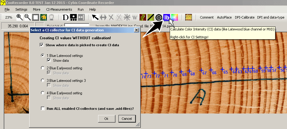
|
After you have defined all your CI collectors, you should see that the blue channel data is also actually created.
When you click the blue lb button you will be questioned which Color Intensity (CI) collector to run. This way you can easily check how the
measurement rectangles are layed out on the image.
|

|
When using "Mean of sorted pixels": After you have set out all your ring width measuring points, you can redefine your image as "DPI and data-type/Dendro-Seasonwood". You can then set seasonwood points. For a pine sample it might often be easily done with the menu command More/Add earlywood/latewood border points, though you have to check the setting for all these points. If you then generate CI data (use the blue lb button!) CooRecorders job of finding the latewood data will be made much easier than otherwise. When this is used for earlywood data generation, there is no longer a risk that any light areas within the latewood will be considered as earlywood, as there is now a well defined border between the two wood types. |
Saving your blue channel data
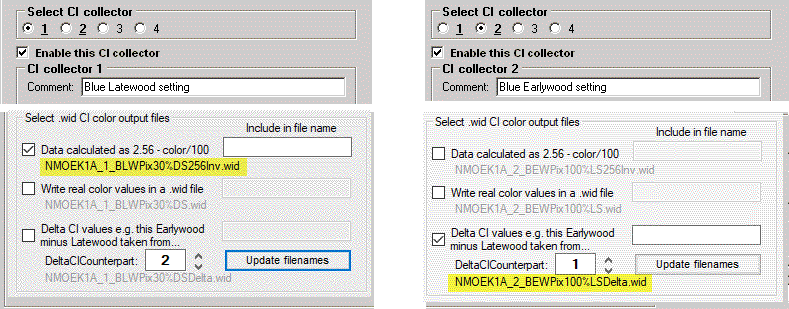
Color values as BI=67 will be written as BI/100, i.e. as 0.67 Any zero value for a color will be written as 0.001 to keep the real zero value as an indication of a missing ring (or missing blue value) as used in both CDendro and CooRecorder. Note: In the example above there are only two enabled CI collectors which will produce two .wid files when checked as shown here. Real blue color values have a negative correlation to the corresponding ring width data. With a small modification of the blue channel data, its variations can be made to correlate to the variations of ring width data. A simple method is to use the algorithm "Inverted_color = 2.56 - BI/100"You can request a .wid file calculated that way by checking the appropriate checkbox shown in the example above. |
CDendro: Looking at correlations
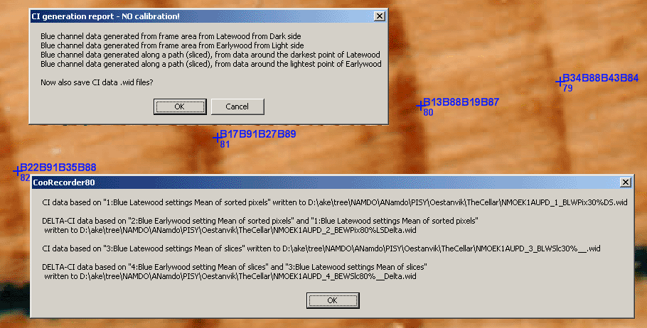
| In this case I have set up the CI collectors to generate two blue-delta files, one for each method, i.e. one based on "Sorted pixels" and one based on "sliced path". I have also requested a blue latewood file from each method. First I got a message telling what had been generated and a question if the .wid files should be generated. |
|
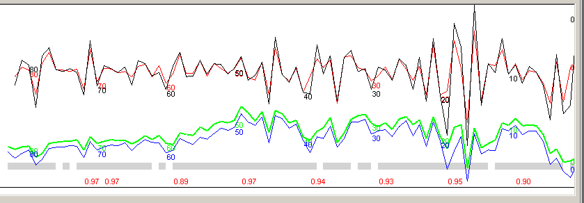
The two delta-blue files matched each other with a correlation of 0.91 (normalized data, upper curve).
The green curve is based on the "Sorted pixels method" and has a mean value of 0.98 while the other curve based on the "sliced path method" has a mean value of 0.85. |
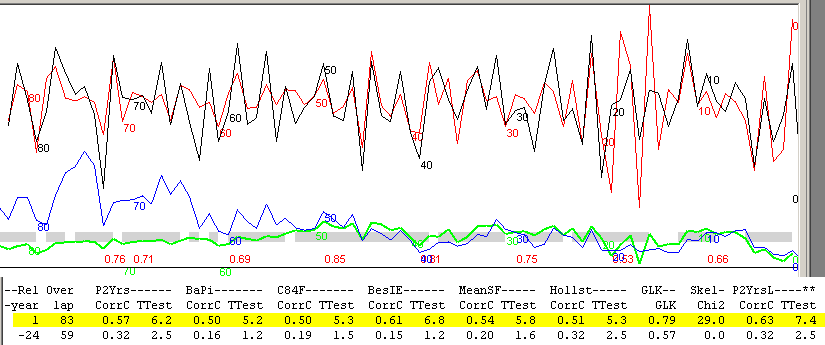
| Sliced path method: When matching the delta file to the ring width file the correlation between normalized curves was in the range 0.50 - 0.63 depending on the normalization method used. There is a clear discrimination between the best match and the next best match. |
| Sorted pixels method: When matching the delta file to the ring width file the correlation between normalized curves was in the range 0.57 - 0.67 depending on the normalization method used. There is a clear discrimination between the best match and the next best match. |
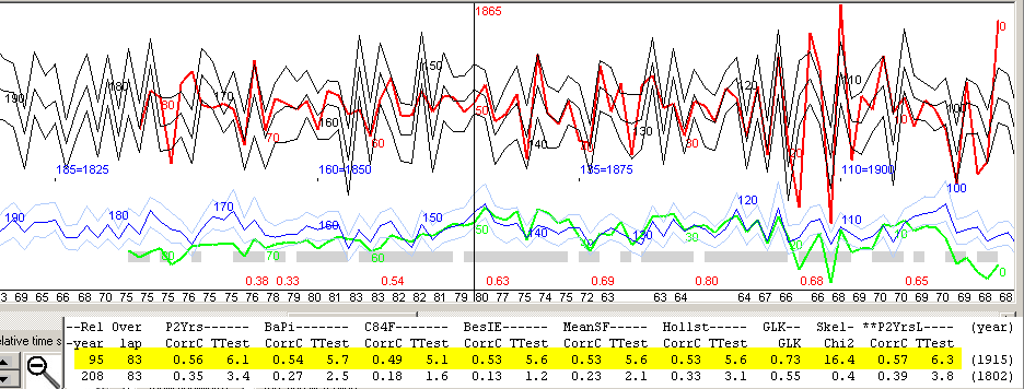
| Sliced path method: The delta file matched to a ring width reference. The younger part (right) matches best. Another test using the "sorted pixels" method revealed about the same results. |

| The oldest 34 years have a correlation of 0.42 towards a mean value reference ring width curve, while the youngest 50 years have 0.65. Possibly some soxhleth cooking had made a difference for the older part containing more tar!? |
|
When CooRecorder has found out where to place a frame across a ring width border - including latewood and some earlywood, then it is time to find out what is a proper blue mean value shade for the darkest latewood of that frame. CooRecorder uses an algorithm that looks at all pixels within the frame and sorts them into dark pixels and light pixels. This algorithm adapts to the "background light" to really divide the frame pixels into two groups. If all pixels are dark, there will anyhow be two groups: one darker than the other. After finding that "threshold color index value", CooRecorder knows how to sort the frame pixels into latewood pixels and earlywood pixels. If a pixel has its blue color index below the threshold it is a latewood pixel otherwise an earlywood pixel. By looking at each pixel of the frame, CooRecorder can now calculate how many latewood pixels (latewoodCount) there are within the frame. Then we want to calculate a mean blue value for those 30% (settable) of all the latewood pixels which are also the darkest among the latewood pixels.
To find a proper blue mean value for this group we will first count how many pixels there are for each blue shade within this group. A simple way to do this is to set up an array of 256 elements, colorCount[0..255] where each element colorCount[colorIndex] holds the number of latewood pixels which have their blue shade equal to colorIndex. We may then calculate the blue mean value like this: Dim darkCount as Integer = 0.30 * latewoodCount 'Number of dark blue pixels to collect for the blue mean value Dim collectedPixels as Integer = 0 'current counter for pixels already collected Dim toFetch as integer = 0 Dim bluesum as Integer = 0 For colorIndex as Integer = 0 to 255 'Loop through the colorCount array and collect the very darkest pixels. If collectedPixels < darkCount Then toFetch = darkCount - collectedPixels If toFetch > colorCount[colorIndex] then toFetch = colorCount[colorIndex] bluesum += toFetch * colorIndex collectedPixels += toFetch Else Exit For End if Next colorIndex Dim meanBlueDarkColorIndex as integer = bluesum / collectedPixels
|

